


CHINA J-VALVES Offers Various High-quality I ndustrial Ball Valves
J-VALVES, a distinguished professional ball valve manufacturer rooted in China, takes pride in its extensive product portfolio. Our offerings span a wide range, including trunnion-mounted ball valves, floating ball valves, high-temperature ball valves, high-pressure ball valves, metal-sealed ball valves, ultra-low temperature ball valves, DBB ball valves, Three-way And Four-way Ball Valve, and fully welded ball valves. Each product is a testament to our commitment to precision engineering and reliable performance. Meticulously crafted, they are designed to not only meet but exceed the most stringent industrial demands, ensuring stable operation even under extreme conditions. This enables us to provide our clients with high-value services and makes our valves widely sought-after in industries.
Product Category
Contact Us


-
J-VALVES-Q41F
-
J-VALVES
Overview of the J-VALVES 1.5 Inch C95800 Floating Ball Valve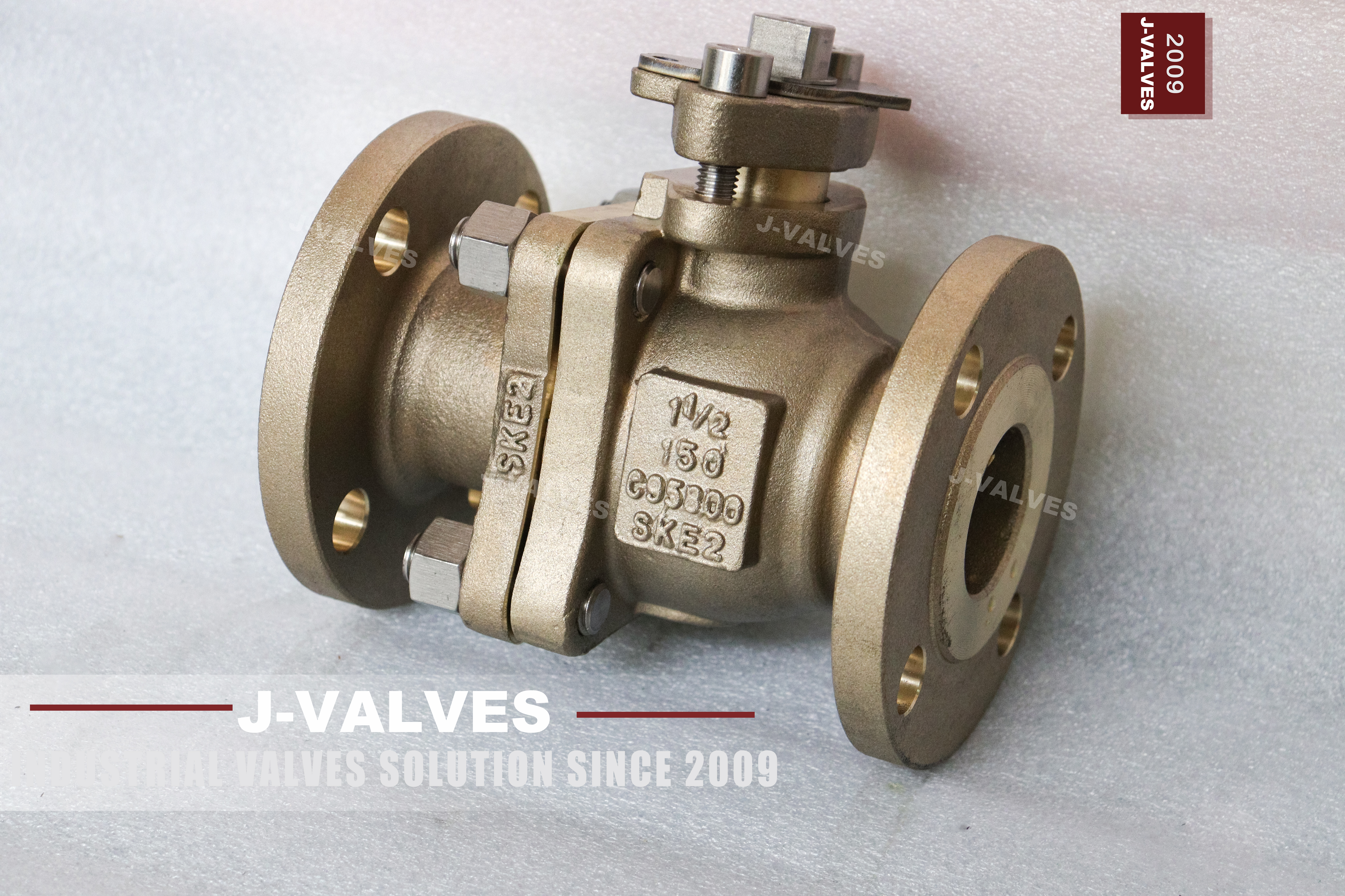
The valve in these photographs is a two piece side entry floating ball valve cast in ASTM B148 C95800 nickel aluminum bronze, with a nominal bore of 1.5 inch, a Class 150 rating and raised face flanges. Four lines are cast into the body before machining: the size 1 1/2, the class 150, the alloy C95800, and the works number SKE2. Those four lines are the whole specification, and anything a buyer needs that is not on them belongs on a separate plate or in the certificate rather than in the casting.
Class 150 is the lightest rating in the B16.24 series, and it is where most seawater cooling and desalination branches sit. At this class the valve is not a pressure problem; the body has more wall than the line needs at any normal seawater temperature, and the flange is thicker than the pipe flange it meets. The decisions that actually matter are the alloy, the seat compound, the bolting, and one detail that is easy to miss: which flange standard the four bolt holes were drilled to, because the rating table and the drilling table are two different documents even when both carry the number 150.
That last point is the reason this page exists. At 1.5 inch, ASME B16.5 Class 150, EN 1092-1 PN 16 and JIS 10K 40A all use four bolts. Three different flanges, three different bolt circles, the same number of holes, and an outward appearance that a photograph cannot separate. A buyer who checks the hole count and stops there will order the wrong valve, and the error shows up on site with the valve in hand and the pipe already cut and supported, which is the most expensive place to discover it. The only measurement that separates the three is the bolt circle, read together with the bolt diameter and the flange thickness.
Design and Construction of the Two Piece Floating Body
The body is split into a main body and one end cap, with a single bolted joint between them. On this size the joint carries four studs through lugs cast into both halves, and the seal at the joint is a flat gasket in a recess machined into the main body. The end cap is located by a machined spigot that enters the main body bore, so the two halves align on metal before the studs are tightened and the gasket is compressed by a controlled amount rather than by whatever the fitter pulls. One joint means one potential leak path to the atmosphere, which is why the two piece pattern dominates at 1.5 inch rather than the three piece pattern used from three inch upward.
The ball floats. It is not carried on a stem or a trunnion; it sits between two seat rings and the upstream pressure pushes it onto the downstream seat. That is the whole sealing principle of a floating valve, and it is why the seat at the downstream side does the work while the upstream seat is only asked to hold during a reversal. At 1.5 inch the force the pressure puts on the seat is small enough that the seat does not need spring assistance or a piston effect, and the upstream seat is left free to lift slightly when the cavity pressure rises, which is the self relieving behaviour a soft seated floating valve has by construction.
The stem enters through the body neck, passes through a gland and is finished as a square drive with a locating plate above it. No lever is fitted in the photograph, which is deliberate: a bare square stem with a plate allows the handle to be supplied loose and fitted at commissioning, so the valve cannot be operated by whoever walks past it during construction. The gland is inside the pressure boundary at the body neck rather than at the top of an extension, which is the arrangement to look for when a valve is going to be lagged. The stem also carries an anti static path from ball to body, which API 608 requires on a soft seated valve so that a static charge built up by flowing hydrocarbon cannot discharge across the seat.
| Component | Standard Material | Optional Upgrade | Service Notes |
|---|---|---|---|
| Body and end cap | ASTM B148 C95800 cast nickel aluminum bronze | C95500 where higher tensile strength is asked for | One heat, one works number on both castings |
| Ball | C95800, polished | 316 stainless, hard chrome on request | Spherical lap, not a turned ball |
| Stem | Nickel copper alloy to UNS N05500 | 316 stainless | Square drive with locating plate, lever supplied loose |
| Seat | RPTFE | PTFE, PEEK, metal seat | Seat compound sets the temperature ceiling, not the body |
| Packing | PTFE V rings | Flexible graphite, low emission set | Gland at the body neck |
| Gasket, body joint | Non asbestos fibre | Graphite spiral wound, rubber bonded | One joint only on a two piece body |
| Bolting | A193 B7M with A194 2HM nuts | 316 studs with 8M nuts | B7M is carbon steel and is the weakest link in seawater |
| Flange facing | Raised face to B16.5 | Ring joint on request | Drilling to B16.5, thickness and rating to B16.24 |
| Operator | Bare stem, lever loose | Worm gear, pneumatic, electric | No mounting pad cast on this body |
Material Options and What the Alloy Actually Does
C95800 is a nickel aluminum bronze with roughly nine percent nickel, five percent aluminum, five percent iron and one percent manganese in a copper base. The aluminum is what forms the passive film; in seawater it rebuilds within hours of being scratched, which is why the alloy survives abrasion that would strip a paint system off carbon steel. The nickel raises the resistance of that film to chloride attack, and the iron refines the cast grain structure so the alloy does not lose toughness in heavy sections. The manganese acts as a deoxidiser during melting, which is a casting benefit rather than a service one, but it is the reason the composition is quoted as a five element range rather than as copper with a single addition.
C95500 is the sister grade, with more aluminum and no nickel addition in the same proportion, giving higher tensile strength and lower elongation. Where a buyer has been offered both under the loose description of nickel aluminum bronze, the difference matters at the flange: C95500 is stronger and less forgiving, C95800 is the grade that is normally chosen for a body that will sit wet for twenty years. Both are covered by B148 and both are rated by B16.24.
The trim is where a seawater valve is usually specified badly. RPTFE is the standard seat and is the right default for cold seawater; PTFE and PEEK extend the ceiling but buy nothing on a line that never exceeds ambient. The ball and stem options matter more than the seat. A C95800 ball with a 316 stem is a common and sensible split, but the bolting is the part that decides whether the valve is still openable after five years: A193 B7M studs are carbon steel, they sit in the most exposed position on the valve, and they will corrode before the body does.
Technical Specifications
The table below separates the two kinds of row a specification sheet always mixes. One kind is fixed by the standard and cannot be varied: the bore, the face to face length, the flange drilling, the test pressures. The other kind is a choice the buyer makes and the works records: alloy, seat compound, bolting grade, operator. Reading the two kinds as if they were the same is how a buyer ends up thinking the length is negotiable because the seat was.
There is no temperature number in this table on purpose. A cast copper alloy body is rated from the B16.24 table at the design temperature, and that table is read rather than calculated; writing a single range across the top of the sheet would say that the valve holds the same pressure hot as cold, which it does not. What is stated instead is the ceiling that applies to the seat compound ordered, because in practice the seat gives out before the body does.
Two rows deserve a note before the table is read. The metric designation row records that PN 20 is what API 6D clause 7.2 writes against Class 150; it is a designation, not a second rating, and it does not mean the flange is a European flange, which is a distinction that catches both buyers and inland sales offices. The flange note row records the arithmetic that catches most buyers at this size: three standards, four holes each, and three different bolt circles, with only the bolt circle telling them apart. The bore row is quoted from the API 6D table rather than measured, because a full bore valve at this size has a bore fixed by the standard and not by the foundry.
| Item | Value |
|---|---|
| Product type | Two piece side entry floating ball valve, soft seated |
| Nominal size | 1.5 inch, DN40 |
| Pressure class | ASME Class 150, cast as 150 on the body |
| Metric designation | PN 20, the designation API 6D clause 7.2 writes against Class 150 |
| Rating basis | ASME B16.24, read at the design temperature |
| Rating note | ASME B16.34 has no copper alloy group and cannot rate this body |
| Body material | ASTM B148 C95800 cast nickel aluminum bronze |
| End connection | Raised face flanged, drilling to ASME B16.5 Class 150 |
| Bolting at flanges | Four holes at this size and class |
| Flange note | B16.5, EN 1092-1 PN 16 and JIS 10K 40A all use four holes here |
| Face to face | ASME B16.10 for NPS 1.5 at Class 150 |
| Bore | Full bore to API 6D Table 1 for NPS 1.5 |
| Stem drive | Square, with locating plate, lever supplied loose |
| Packing location | Gland at the body neck, inside the pressure boundary |
| Body joint | One bolted joint, flat gasket in a machined recess |
| Anti static | Ball to body device to API 608 |
| Fire safe | Metal shoulder behind the seat, API 607 and ISO 10497 |
| Product standard | API 608, with ASME B16.24 for the rating |
| Test standard | API 598 |
| Certification | EN 10204 3.1, heat number on body and end cap |
| Temperature, alloy | Per ASME B16.24 at Class 150, a table lookup |
| Temperature, valve | Set by the seat compound ordered, below the alloy ceiling |
Standards and Compliance
Three documents govern this valve and they do not overlap. ASME B16.24 carries the pressure temperature ratings for cast copper alloy flanges and flanged fittings at Classes 150 through 2500, and it is the only place a rated pressure for this body can be read. ASME B16.5 governs the drilling: bolt circle, bolt size, number of holes, facing dimensions. API 608 governs the product itself, covering the body joint, the stem retention, the anti static path and the fire safe design.
ASME B16.34 is the document that most data sheets reach for and that does not apply. B16.34 organises its ratings by material group, with groups for carbon steel, the low alloys, the stainless grades and a set of special alloys; there is no copper alloy group in the table. A data sheet that prints a B16.34 rating on a bronze valve has taken a number from a book that does not cover the material, and the number will be wrong in one direction or the other.
A fourth document is worth knowing about even though it does not apply here: ASME B16.15 covers cast copper alloy threaded fittings. The moment the same alloy is made with threaded ends instead of flanges, the governing document changes from B16.24 to B16.15 and the rating table changes with it, so a valve quoted as bronze to B16.24 and delivered with threaded ends has been quoted against the wrong book. That is one more reason to state the end connection in words on the order rather than assuming the alloy decides the standard, and it is why the flange standard appears twice in the table on this page, once as a rating and once as a drilling.
| Requirement | Standard | What J-VALVES Supplies |
|---|---|---|
| Pressure temperature rating | ASME B16.24, Class 150 | Rated pressure at the design temperature, stated on the data sheet as a table lookup |
| Flange drilling | ASME B16.5, Class 150, NPS 1.5 | Four holes, facing and bolt circle to the B16.5 table, measured and recorded |
| Product design | API 608 | Body joint, stem retention, anti static path and fire safe shoulder to the standard |
| Fire safe qualification | API 607 and ISO 10497 | Certificate for the tested size and seat combination |
| Pressure testing | API 598 | Shell and seat test records, both seats tested in both directions |
| Material certification | EN 10204 3.1 | Certificate with the heat number that matches the casting |
| Marking | API 608 and B16.24 | Size, class, alloy and works number cast or stamped as the standard requires |
Manufacturing Process
The body and end cap are sand cast in the same heat, which is what allows one works number to appear on both halves. Pattern work at 1.5 inch is where the casting is won or lost: the wall is thin enough that a cold shut or a misrun appears as a leak path years later, and the seat pocket has to be cast close to size so that machining does not cut through into porosity. Castings are shot blasted, inspected visually and dimensionally, and the alloy is verified by spectrometry on every heat rather than on a sample.
Machining is done in two stages with a stress relief between them. The casting is roughed, the joint face and the flange faces are cut, and the part is then set aside so that the residual stress from casting and roughing can move the metal before the finishing cuts are taken. Skipping that pause is the classic cause of a joint face that is flat on the bench and leaks in service, because the face distorts after the last cut.
The seat pockets are finished to a diameter and a depth that hold the seat ring square to the bore, and the ball is lapped rather than turned. A lapped ball has a spherical form that matches the seat ring around its whole circumference; a turned ball touches on a band and leaks as soon as the seat relaxes. Assembly is done with the ball and seats fitted dry first to check the float, then with the gasket and the studs torqued in a crossing pattern.

Quality Control and Testing
Every valve gets a shell test at one and a half times the rated pressure and a seat test at one and one tenth, both to API 598, with the seat test done on each seat separately in each direction. On a floating valve that matters more than it does on a trunnion valve, because only one seat is loaded by the pressure at a time; a valve that passes with the flow in one direction can still leak with the flow reversed, and API 598 requires both.
Alloy verification is by optical emission spectrometry on the body, the end cap and the ball, with the results compared against the B148 ranges for C95800 rather than against a supplier certificate. The test is done on the finished casting surface after a light clean, not on a test bar, so that what is certified is the metal in the valve. Where the buyer has asked for C95500 the same test distinguishes the two grades, which is worth having because the two are indistinguishable by eye and only one of them was quoted; the aluminium and nickel readings separate them cleanly.
Dimensional inspection covers the flange bolt circle, the facing height, the face to face length and the bore. On this size the bolt circle is the measurement that decides whether the valve will bolt to the pipe, so it is recorded on the inspection sheet as a number and not as a pass mark. Each valve is then marked, the certificate is issued against the heat number, and the flange faces are protected before packing.
| Step | What Is Checked | Standard or Acceptance |
|---|---|---|
| Incoming casting | Wall thickness, seat pocket integrity, visual defects | Works procedure, pattern drawing |
| Alloy identity | Spectrometry against B148 ranges for the ordered grade | ASTM B148, all heats |
| Rough machining | Joint face and flange face allowance after stress relief | Works drawing |
| Ball lapping | Sphericity and surface finish | Works procedure |
| Shell test | One and a half times rated pressure, no leakage | API 598 |
| Seat test | One and one tenth rated pressure, each seat, each direction | API 598 |
| Dimensional | Bolt circle, facing, face to face, bore | ASME B16.5, B16.10, API 6D Table 1 |
| Marking and certificate | Size, class, alloy, works number, heat number | API 608, EN 10204 3.1 |

Applications and Industry Service
The natural home for a 1.5 inch Class 150 bronze valve is a seawater cooling branch: the small lines that feed a heat exchanger, a sample point, a flushing connection or an instrument tap off a larger header. These lines run at low pressure, they are wet all the time, and they are opened rarely, which is a combination that suits a soft seated floating valve and an alloy that does not need a coating. The same duty on a carbon steel valve would need a rubber lining or a corrosion allowance, and neither survives a valve that has to seal on a seat.
Desalination and marine duty follow the same pattern. On a ship, a 1.5 inch bronze valve on a seawater service line is common enough that the flange drilling question is answered by the yard standard rather than by the buyer; the risk appears when a valve is bought for a land based plant that was designed to a European or Japanese flange standard and the purchase order names only the size and class.
The same valve is used on cooling water in refineries, on fire main branches where a bronze body is accepted, and on potable and process water where a coated steel valve would need maintenance. It is not the right choice for steam, for hydrocarbons above the seat ceiling, or for any duty where the seat has to hold with the line dry and hot; those cases go to a metal seated valve in a steel body.

Installation, Operation and Maintenance
The first action at installation is to measure, not to lift. Take the bolt circle and the bolt hole diameter on the mating pipe flange and compare them against the B16.5 table for NPS 1.5 Class 150; if the pipe flange was made to EN 1092-1 PN 16 or to JIS 10K 40A, the four holes will be there and the circle will not match. An adapter or a flange change is the only correct answer; slotting holes or forcing bolts is not, because the studs then load the valve flange off centre and the joint face distorts under torque. Measure the facing height at the same time, since a raised face of the wrong height will hold the flanges apart at the rim and leave the gasket unloaded in the middle.
Bolting deserves its own decision. The standard A193 B7M studs are carbon steel and will be the first part of the assembly to corrode in a wet location, so on seawater duty either specify 316 studs with 8M nuts or fit insulating sleeves and washers and treat the joint as a dielectric break. The second option also interrupts the galvanic couple between the bronze body and the steel pipe, which is worth having when the pipe is carbon steel.
Operation is a quarter turn and nothing more. The locating plate above the stem limits travel to ninety degrees, and forcing past the stop damages the seat rather than opening the valve further. Maintenance on a two piece body means removing the end cap, which on a flanged valve means breaking the pipe joint on that side; the ball and seats come out without disturbing the other flange, but the line has to be opened, and that is the maintenance cost of the pattern.
How to Specify and Order
A purchase order for this valve needs six items to be unambiguous: size and class as numbers, alloy by its B148 designation, flange standard and facing, seat compound, bolting grade, and the operator. Everything else follows from those six, and the failures that reach production are almost always in the second and the fourth: an alloy named loosely as bronze, and a seat named loosely as PTFE when what is wanted is the reinforced grade.
State the flange standard in words even when the class is given, because the class alone does not decide the drilling at this size. A line written as 1.5 inch Class 150 with four holes to ASME B16.5 cannot be mistaken; a line written as DN40 PN16 can, and it is the same nominal bore. Where the two conflict, the drawing wins, and the drawing should carry the bolt circle as a dimension rather than as a note referring to a table.
Where the valve is going into an existing line whose flange standard is unknown, order against a measured bolt circle rather than against a standard name, and ask for the facing height with it. J-VALVES quotes from the drawing for the size, the alloy and the trim ordered, with the certificate issued against the heat number that appears on the valve, and the flange drilling recorded as a measured value on the inspection sheet rather than as a reference to a table.
FAQ
Q: Three flanges use four holes at this size, so how do I tell them apart?
A: By the bolt circle, the bolt diameter and the flange thickness, and by nothing else. At 1.5 inch the ASME B16.5 Class 150, EN 1092-1 PN 16 and JIS 10K 40A flanges all carry four bolts, so counting holes confirms nothing. Measure the bolt circle centre to centre across the flange, measure the hole diameter with a caliper, and measure the flange thickness at the rim; those three numbers separate the three standards, and the hole count does not.
Q: Does the 150 on the body mean 150 psi?
A: No. It is ASME Class 150, and the pressure the valve actually holds at a given temperature is read from the ASME B16.24 table for this alloy at Class 150. The class fixes the flange and the body wall; the rating table converts that class into a pressure at the design temperature, and for a cast copper alloy it is B16.24 that holds the table, not B16.34, which has no copper alloy group at all.
Q: Is C95800 the same as C95500 nickel aluminum bronze?
A: No. They are two grades in ASTM B148 with different aluminium and nickel contents. C95500 is the stronger and less ductile of the two, C95800 is the grade normally selected for a body that sits in seawater for its whole life. A certificate naming only nickel aluminum bronze does not say which one was cast, so the grade should be written on the order and confirmed on the 3.1 certificate against the heat number.
Q: Why is there no temperature range on this page?
A: Because a cast copper alloy body is rated from a table at the design temperature and the number changes with that temperature. Printing a single range across the top of a data sheet would claim the same pressure hot and cold. What is fixed here is the ceiling that comes from the seat compound, because on a soft seated valve the seat fails before the body does, and the body rating is a lookup in B16.24.
Q: Is the lever included?
A: The valve leaves the works with a bare square stem and a locating plate, and the lever is supplied loose. That is deliberate: on a construction site a valve with a handle fitted gets operated by whoever passes it, and a soft seated valve that is cycled with debris in the line damages its seat before commissioning. The lever is fitted when the line is flushed, and the locating plate limits travel to a quarter turn.
Q: Should the bolting be B7M or stainless?
A: B7M is the standard and it is carbon steel, which makes it the first part of a seawater valve to corrode. On a wet location either specify 316 studs with 8M nuts or fit insulating sleeves and washers so the joint becomes a dielectric break. The second route also breaks the galvanic couple between the bronze body and a carbon steel pipe, which is the failure that shows up as pitting on the steel side of the joint.


Hot Products


News
Ball Valve Condition Monitoring: Which Signals Actually Predict A Failure
Torque signatures, acoustic emission, differential pressure and digital twin residuals: which measurements find a failing ball valve early.
Read More
Ball Valves in SWRO Desalination: The High Pressure Section Where Ordinary Seawater Valves Fail
Why SWRO high pressure valves fail early: recovery arithmetic, crevice temperature, ERD ripple, scale, letdown cavitation and surge.
Read More
Air Test And Water Test For Ball Valves: What Each Medium Can Prove
A ball valve can pass a hydrostatic seat test and still leak gas. Why air and water prove different things, and how to read a bubble, decay or helium test.
Read More
Ball Valve Flange Bolting: Preload, Relaxation And The Fasteners That Decide Leakage
A weeping flange is rarely the gasket. Preload, torque scatter, hardness limits and thermal relaxation decide whether the joint holds at 100 bar and 400 C.
Read More