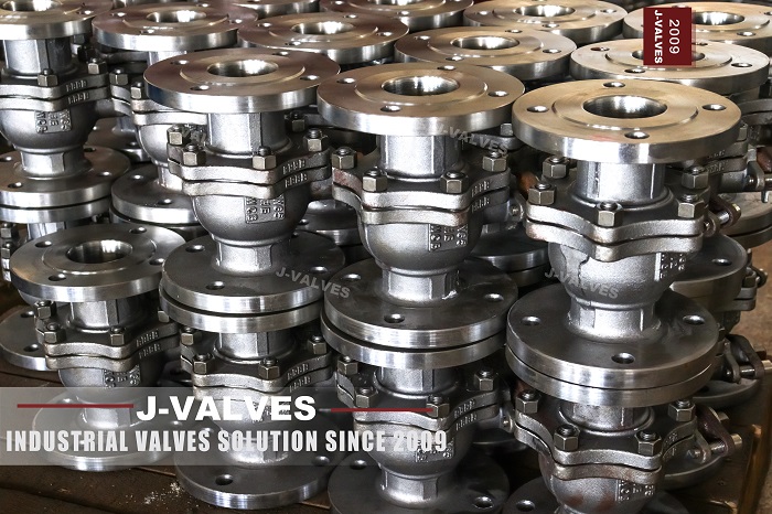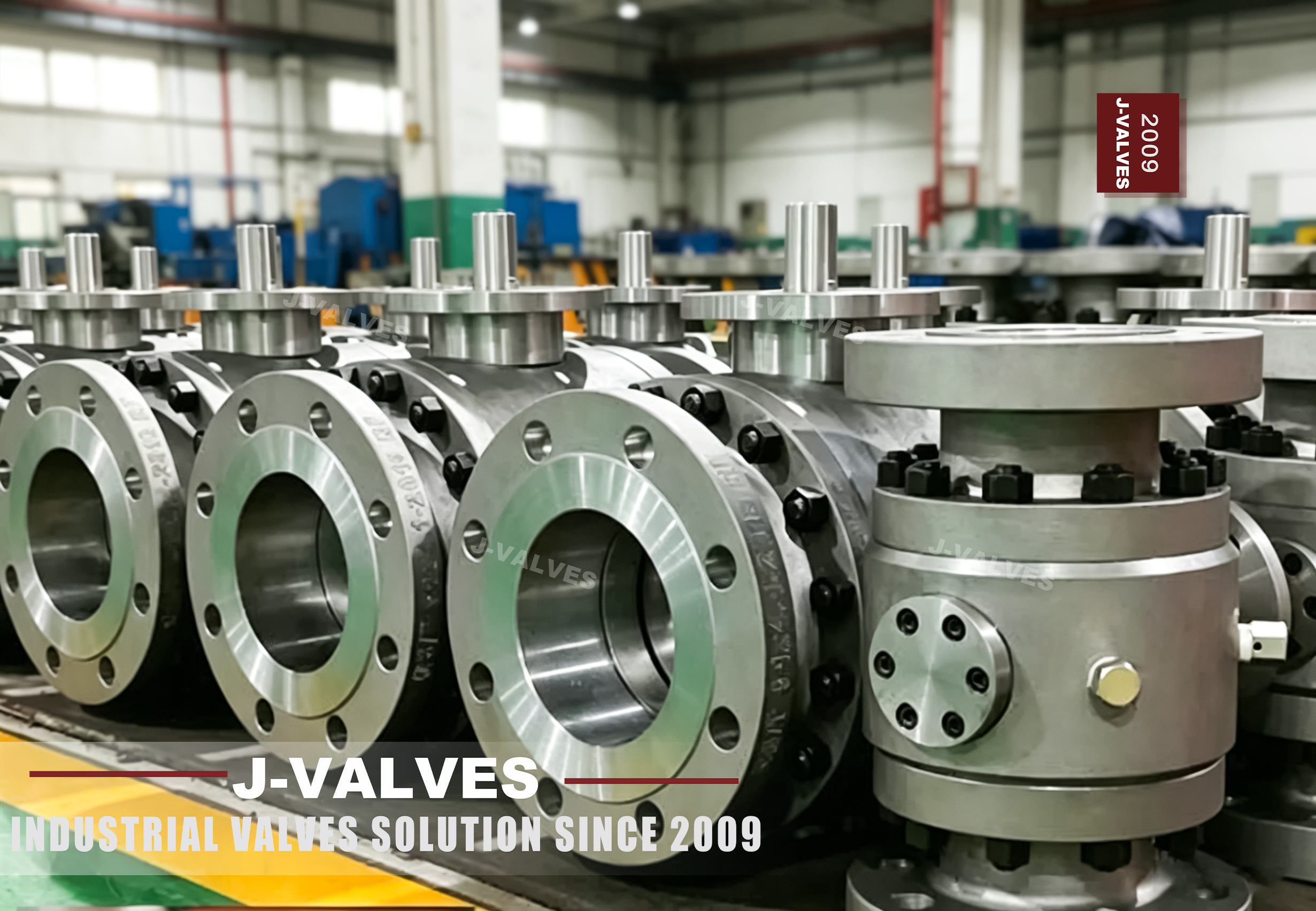


Floating ball valves play a crucial role in industrial fluid control systems, and the 4-inch 300LB cast flange floating ball valve is commonly used in various applications. Selecting the appropriate ball valve and properly maintaining it are essential for ensuring efficient and reliable operation. This article will guide you to understand the key steps and precautions for selection and maintenance.
I. Selection of 4-inch 300LB Cast Flange Floating Ball Valves
1.1 Defining Application Requirements
Firstly, clearly define the application scenarios. Determine the type of fluid that needs to be controlled, such as water, oil, gas, or corrosive chemicals. Different fluids have different impacts on the materials and sealing performance of the valve. Meanwhile, also pay attention to the working temperature and pressure ranges. The 300LB rating indicates the pressure rating of the valve, so it is necessary to ensure that the working pressure of the system is within this range to guarantee safety and functionality.
1.2 Material Considerations
The casting material is of great importance. For the 4-inch 300LB cast flange floating ball valve, common valve body materials include WCB (carbon steel), stainless steel (such as 304 or 316), and alloy steel. WCB is suitable for general industrial applications involving non-corrosive fluids. When dealing with corrosive media or environments requiring higher corrosion resistance, stainless steel is the preferred choice. Consider the chemical compatibility between the fluid and the valve material to prevent corrosion and extend the service life of the valve.
1.3 Sealing Performance
Sealing is a key factor affecting the performance of the valve. There are mainly two types of seals: soft seals (using materials such as polytetrafluoroethylene) and metal seals. Soft seals can provide excellent sealing performance at lower pressures and temperatures, ensuring tight closure. Metal seals are more suitable for high-temperature and high-pressure applications, as soft materials may fail in these applications. Evaluate the required sealing tightness and working conditions to select the appropriate seal type.
1.4 Flow Characteristics and Control Requirements
Consider the flow characteristics required by the system. Floating ball valves usually have good flow capacity and can provide on-off or throttling control. If precise flow control is needed, check whether the valve design allows for it. In addition, determine whether additional functions are required, such as position indicators, actuators (manual, pneumatic, or electric), or integration with the control system, to meet the operational requirements.
II. Maintenance of 4-inch 300LB Cast Flange Floating Ball Valves
2.1 Regular Inspection
Develop a regular inspection plan. Visually inspect the valve for signs of leakage, corrosion, or physical damage. Check whether there are problems with loose bolts or gaskets in the flange connections. Check whether the valve stem is worn or there is leakage around the valve stem packing. Early detection of problems through regular inspections can prevent major failures and costly downtime.
2.2 Lubrication
Proper lubrication is crucial for the smooth operation of the valve. Lubricate the valve stem and other moving parts according to the manufacturer's recommendations. Use appropriate lubricants that are compatible with the valve material and the fluid being handled. Regular lubrication can reduce friction, prevent jamming, and extend the service life of the moving parts.
2.3 Cleaning
Regularly clean the valve, especially when it handles fluids containing impurities or deposits. Accumulated debris can affect the sealing performance of the valve and cause wear. Disassemble the valve to clean the internal components and ensure that all channels and sealing surfaces are free of contaminants.
2.4 Replacement of Seals and Gaskets
Over time, seals and gaskets will wear out and need to be replaced. Monitor the valve for any signs of leakage, which usually indicates that the seals have worn out. When replacing seals and gaskets, use high-quality replacements that match the original specifications. Ensure correct installation to maintain the integrity of the seal.
2.5 Actuator Maintenance
If the valve is equipped with an actuator, perform maintenance according to the actuator manufacturer's instructions. This may include checking electrical connections, air supply, lubrication of actuator components, and calibration to ensure accurate valve positioning.
III. Conclusion
Selecting a 4-inch 300LB cast flange floating ball valve requires a deep understanding of application requirements, material compatibility, sealing requirements, and flow control requirements. Proper maintenance, including regular inspections, lubrication, cleaning, and timely replacement of components, is essential for ensuring that the valve operates efficiently and reliably throughout its service life. By following these guidelines, you can maximize the performance and service life of the floating ball valve and contribute to the overall efficiency and safety of the fluid control system.